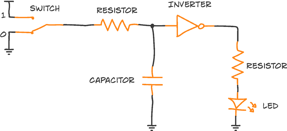
Below you can see the circuit we’re currently talking about.
The resistor and capacitor on the left of the inverter make up an RC delay element:
But how does the current flow in this circuit?
If you try to follow the current flow you might end up scratching your head.
The inverter actually has connections to plus and minus. To simplify, these are usually hidden in circuit diagrams. You just need to know that they’re there.

10 Simple Steps to Learn Electronics
Electronics is easy when you know what to focus on and what to ignore. Learn what "the basics" really is and how to learn it fast.

This means it’s not as easy as “what goes in, must come out” since the current can flow into and out from the plus and minus connections too.
But one important thing to keep in mind when you have logic gates is:
No current flows into the input.
And you can think of the output as either connected directly to plus (if it’s 1) or minus (if it’s 0).
This means we can look at the left and the right side of the inverter individually.
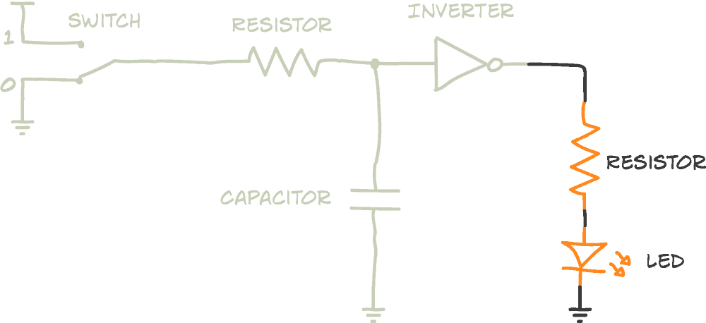
Current flow on the right side
The right side of the inverter is simple:
If the inverter outputs a 1, currents flows down from the inverter output, through the resistor and LED, down to minus.
If the inverter output is 0, no current flows on the right side.
Current flow on the left side
The left side of the inverter takes some more concentration.
But remember our rule:
Current always flows from a higher to a lower voltage – if there is a path for the current to take.
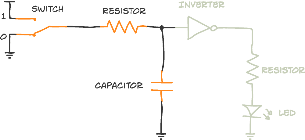
When you flip the switch from 0 to 1, the left side of the switch is connected to plus. The capacitor is currently discharged, so it has 0 volts across it. This means there is a path from plus through the resistor and capacitor, down to minus – therefore current will flow.
When the capacitor is fully charged, it doesn’t allow any more current to flow through it. So the current flow stops.
“Fully charged” means the voltage across it has reached the voltage it is being charged with.
When you flip the switch back again from 1 to 0, do you see where the current flows?
Before you answer that, here’s an important fact: A capacitor will always discharge in the opposite direction of how it was charged!
So it looks like the current is flowing backwards..!
But, as you now realize, current simply flows from higher voltage to lower voltage. If voltages change – and they often do – the current redirects from the new ‘high’ to the new ‘low’.
So you now have a positive voltage on the capacitor. The switch is connected to 0 volts. And there is a path from the capacitor, through the resistor and down to minus through the switch. So current will flow here.
The current flows until the capacitor is fully discharged (i.e. no more voltage across the capacitor) making it the same voltage (ie zero) as the minus of the battery.

Get Our Basic Electronic Components Guide
Learn how the basic electronic components work so that circuit diagrams will start making sense to you.
Fascinating!
Glad you like it!
where to buy these components
Very interesting and easy to understand thx
Glad to hear!
I love the way you teach!
That’s very cool to hear =)
what is the equation to figure out time delay? and how do you do it?
The capacity of the capacitor in Farads X the resistance of the resistor in Ohms = the delay in seconds
The time delay equation is T=R×C
Where T is time, R is resistance and C is capacitance
What happens to the capacitor in the circuit is now clear. But I don’t see any description what happens to the resistor + LED part… When the switch is at 0V and the capacitor starts discharging, there is a path to the plus, but what happens to the LED at that moment?
On the LED side of the circuit, all depends on if the output is HIGH or LOW. When HIGH, the LED is on. When LOW, the LED is off.
The inverter has a threshold voltage that decides exactly when to switch the output on or off. In this circuit you need to use a Schmitt-triggered inverter where the threshold voltage for going from low to high is a bit higher than the one for going from high to low.
I am still confused.
The switch set to zero passes no current, so the inverter uses its own connection to plus to power the right side of the circuit.
When the switch is set to 1, the inverter senses current on the left side and turns off the circuit on the right side of the inverter.
But when the switch is off, the current is still coming, just now it is coming from the discharging capacitor.
So it seems like the left side always has current, either from the switch or from the capacitor. Either way the inverter should see high voltage on its left, and therefore the current on the right side of the inverter should always remain off.
So how does the light ever turn on?
Hi Scott,
The inverter does not sense current. It senses voltage levels.
At the beginning, with the switch at 0, there is no voltage on the left side. So the right side is on, powering the LED.
When the switch is set to 1, current flows through the capacitor and charges it so that the voltage across it raises. And after a short delay, the voltage is high enough for the inverter to detect it and turn off the right side.
When the switch go back to 0, the capacitor starts to discharge towards the 0 through the switch. As the capacitor discharges, the voltage across it decreases, and after a short delay it’s low enough for the inverter to detect it as a low voltage and turn on the right side again.
This makes more sense and I have a good understanding now. Thanks you so much admin. Your presentations are so clear. It makes electronics more interesting
Can we say that when the switch is “1”, the capacitor gets charged till it is fully charged AND the input of the inverter is high, which makes the output low (which means the LED is off).
And when the switch is set to “0” (and the capacitor was already charged), current flows from the positive capacitor to the swtich to ground AND it keeps the input of the invertor still high as long as the capacitor is not fully discharged (which means the LED stays off till the capacitor is fully discharged)?
Yes, that’s pretty much it =)
Hi
I’m trying this using a 741 inverter. 9v supply to pins 7&4 input to pin 2 output to pin 6.. When connecting to pos supply , the led glows dimly , and then when connect to negative it glows brightly.
This I can see this is the effect of high input low output and low input high output of the inverter.
But I am puzzled as to where the voltage is comming from, to make the led glow although dimly, when there is a high input, eg connected to pos supply.
There should be zero output?
Like your emails, and easy explanations ,will probably join your site after the summer.
Hi Clive,
The 741 is an opamp, not an inverter, so it will amplify the difference between what is on the input pins 2 and 3. Are you sure you’ve set it up as an inverter?
Hi.
Ah. I seem to be missing the point, and as my lack of knowledge , has shown ,just because the pins are called inverting and non-inverting , does not mean it’s an inverter. I found a flashing light diagram on the web, also with feed back loop, and this worked. But as I say it flashed , but I guess was not inverting.
Ok lesson learnt .
As I’m learning , what numbers are inverters, i might have one in kit of bits I have.
I’ll look out for the next email.
Thanks
i must admit i’m a little confused, i’m trying hard to understand the capacitor, when you say;
“And there is a path from the capacitor, through the resistor and down to minus through the switch. So current will flow here.”
would not the current take the less resistive path and flow from its ground connection ? it may be that i’ve completely miss understood capacitors.
when a capacitor is being charged a negative charge builds up on its negative plate & a positive charge builds up on its positive plate, and once its charge equals that of the supplies, no more current flows, when you flip the switch from 1 to 0, thats what i don’t understand, is the 0 terminal connected to the negative plate of the capacitor ? very sorry if i sound confusing, if someone could please point out where i’m getting mixed up that’d be great, thank you
Hi Muhammad,
“would not the current take the less resistive path and flow from its ground connection?”
Current always from flow a high potential (Volt) to a low potential (Volt). Since ground is the lowest potential in this circuit, you won’t have current flowing from ground and back into the circuit.
ah yes thank you, also when you say;
‘Which means there is a path from plus through the resistor and capacitor, down to minus – therefore current will flow.’
does the current literally flow through the capacitor ?
Yes, current flows through the capacitor unless it’s fully charged.
Why does the current go backwards instead of going to the inverter and from there to neutral?And also what type of inverter is the inverter (nmos,pmos etc.)?
The inverter only cares about voltage. It looks at the voltage on its input and sets the output to the opposite.
No current flows into the input because of the way the inverter is built (ok, a tiny bit of current does flow when the input is high, but usually so little that you can ignore it)
The inverter type for this circuit to work needs to be a schmitt-triggered inverter. It doesn’t matter what transistor types are used to build it.
Put more simply, is the voltage that crosses the inverter at ’14’ and ‘7’ meant only to ‘activate’ the inverter, or am I completely missing something?
Yes, that’s correct – it only activates the inverter.
I have the same question as Muhammad and don’t understand your answer. It’s not apparent to me why current would flow backwards through the resistor and switch to ground and not forwards in the RC element to ground. Forward seems (literally) the path of least resistance. Also, I guess when I think of DC circuits I have always thought that meant current travels one-way.
“Forward seems (literally) the path of least resistance.”
The current does *not* take “the path of least resistance”. That’s a misunderstanding. Current takes ALL paths it can take from positive to negative voltage potential.
I think current take the path of least resistance (or impedance) that’s true from an EMC perspective?
So if the input to the inverter is 0 or “no voltage”, does the output 1 voltage required to power the LED come from inverter’s separate connection to +? The one that you say is typically hidden in the circuit diagram? Thanks.
Yes, that’s correct.
Wow, I’m also a bit confused. First, let me explain that I understand the following:
1 – Current flows from HIGH to LOW voltage.
2 – When the switch is at position 1, current flows from the power source through R1 down to the capacitor, and then finally to ground.
3 – When the capacitor is fully charged, no more current flows through it.
4 – When the switch is turned off, current flows from the capacitor back through R1, then back to the switch and down to ground.
What I don’t understand:
1 – When the switch is at position 1, wouldn’t the current flow not only down to the capicator but also to the inverter as well? And since the current causes a 1 on the Inverter’s input, this would mean that the output is 0 and the LED stays off, however the inverter still has a separate connection to the + and – of the power source so what happens to that current flow?
2 – When the switch is at position 0, this means that the current from the capacitor not only flows to R1 and then back to the switch, but also to the Inverter as well, which means that a 1 will be on the input of the inverter and thus a 0 on the output, so the LED will continue to have no current flowing to it, therefore it will remain off. Is this correct?
3 – Does the inverter continue to receive current regardless if the switch is at position 1 or 0, since the inverter has a direct connection to the power source? If so, wouldn’t current flow to R2 and then to the LED causing it to light up ALWAYS? I guess I’m not understanding how the direct connection to + and – of the power source and the Input and Output work together on the inverter.
Is that when there is a 1 on the Input of the Inverter that the direct connection to the + and – of the power source is ignored, and therefore the Output will be a 0 (meaning no current), so the LED stays off, BUT, if there is a 0 on the Input of the Inverter, then the direct connection to the power source is activated, making current flow to the Output of the Inverter and thus lighting the LED?
4 – Is this LED in this circuit supposed to BLINK, because I don’t see/understand how the blinking happens.
I’m so confused, I hope someone can help me better understand this circuit and the flow of current, and when the LED actually receives current to light it up.
You should know that I just took an interest with electronics and I only just started, so I apologize if what I am asking is too basic. I understand Ohm’s law and built my first simple LED circuit on a breadboard with a PIR sensor, but that’s about it.
Thanks in advance for your answers, and Happy New Year 2020!
Thanks,
Alan
No current flows into the inverter. The inverter only responds to changes in voltage on it’s input.
(Okay, a tiny bit of current flows when the input is HIGH, but it’s so little that you can think about it as if no current flows).
Hey, I’m Swainson. Just wanted to say that I love the way you explain electronics. Really feel like I’m learning this thing now. Finally! But could you some me how to calculate voltage (potential difference) in sub-loops, and loops within sub-loops. Thanks much in advance, would really apprecilove that.
The short answer is to use Ohm’s law and logic. But if you give me a specific example I can give a more specific answer on how to find the voltage for that example.
great job.. Thank you for all your knowledge.. learning lot’s as i go.. keep them coming!
I think the key to the function of the capacitor in this circuit is the knowledge that current does NOT flow through the invertor – ONLY through the capacitor – otherwise the current would split and go to the capacitor AND through invertor so the former would have little or no effect on the right hand side.
Yes, very important point!
Hi. My name is Jamie and Im following this as lesson 4, started on Monday. I like several others have commented am finding the lessons interesting and enjoyable for a layman and enjoy the way everything is presented. Very good. However .. at lesson four Im wondering if there is a future for me in electronics. I think the problem came when you pose the question …
…. When you flip the switch back again from 1 to 0, do you see where the current flows?….
… well maybe not…. because you say it goes to the switch. I did not get that because, I thought it went to the LED. In the YouTube video you very helpfully show that when the switch is turned off the capacitor discharges its charge and makes the LED glow until it is discharged.
I see several other questions have come up here so Im clear that Im missing something still. Be grateful if you help with my misunderstanding.
Thanks in advance.
Hi James,
Current does not flow into the inverter. I mention it in the article, but I should emphasize it more as it is important to understand.
So current cannot flow anywhere but back through the resistor and down to ground.
Best,
Oyvind
Hey guys! So there has been a lot of good questions on here, this unfortunately is not one of them.
So while looking over the above diagram, when we turn off our switch (0), why does the current flow back to the switch instead to the minus under the capacitor. I think I’m missing something simple here sorry.
Hey LBP!
That’s because a capacitor is always discharged in the opposite direction of how it was charged.
The capacitor was charged by current flowing down to the minus under the capacitor, so it can only discharge upwards.
It’s similar to a battery: The current will never flow back into the battery from the plus terminal towards minus.
Is there any video for this one? I think I understand it, but it would be helpful to see the led lighting up.
I think that while the capacitor is charging, the led is on. Once it is fully charged it is off. While it is discharging it is off and once it is fully discharged it is on again.
The comment about the capacitor always discharging in the opposite direction was helpful in understanding it – perhaps it could be in the email?
Yes, it is. You’ll find it here:
https://www.build-electronic-circuits.com/build-blinking-light-circuit/
And it’s a good idea to put the sentence about discharging in the opposite direction into the emails. I’ve just updated lesson 4. Thanks for your input!
This is good.
1. But how does the inverter detects/senses in the input that the voltage is high enough it for it trigger zero or low enough to trigger high in the output ? Since there’s a capacitor connected.
I know the lesson is based on the operation mechanism of the capacitor and I really understand it very well since it provides delays. It seems like, before the delay already the inverter would have decided, that’s y we see the trails through the capacitor operations.
Does this mean I would have to look into the inverter datashet? Types and operation? Since you pointed out in your answers that there’s a threshold in the inverter? For it to trigger whichever state?
An inverter can be built with a transistor. And in it’s simples form the threshold would be the threshold voltage of the transistor.
The Schmitt inverter adds some extra complexity to have different high-to-low and low-to-high thresholds.
Here’s how a basic inverter could be built using a transistor: https://www.electronics-tutorials.ws/logic/logic_4.html
Thank you so much. Your teaching style is very clear and concise. I’m a dad who used to make all manner of electronic things as a youngster. Now I’m relearning so I can pass on the passion to my own kids. You have provided a marvellous resource and from where I sit, it stands tall in a big field of other electronic learning sites. Many thanks from Sydney, Australia! Dave
Hi Dave, I’m very happy to hear that!
Cheers!
Oyvind
Dear Sir, in these comment section on January 2,2020 Mr. Alan has asked really important queries, request you to kindly clarify all these queries, this will be really a good help in clearing doubts.
Regards
Sandeep Mehta
Dear Sir,
Kindly clear all these doubts as asked earlier by Mr. Alan on January 2, 2020.
1 – When the switch is at position 1, wouldn’t the current flow not only down to the capicator but also to the inverter as well? And since the current causes a 1 on the Inverter’s input, this would mean that the output is 0 and the LED stays off, however the inverter still has a separate connection to the + and – of the power source so what happens to that current flow?
2 – When the switch is at position 0, this means that the current from the capacitor not only flows to R1 and then back to the switch, but also to the Inverter as well, which means that a 1 will be on the input of the inverter and thus a 0 on the output, so the LED will continue to have no current flowing to it, therefore it will remain off. Is this correct?
3 – Does the inverter continue to receive current regardless if the switch is at position 1 or 0, since the inverter has a direct connection to the power source? If so, wouldn’t current flow to R2 and then to the LED causing it to light up ALWAYS? I guess I’m not understanding how the direct connection to + and – of the power source and the Input and Output work together on the inverter.
Is that when there is a 1 on the Input of the Inverter that the direct connection to the + and – of the power source is ignored, and therefore the Output will be a 0 (meaning no current), so the LED stays off, BUT, if there is a 0 on the Input of the Inverter, then the direct connection to the power source is activated, making current flow to the Output of the Inverter and thus lighting the LED?
4 – Is this LED in this circuit supposed to BLINK, because I don’t see/understand how the blinking happens.
I’m so confused, I hope someone can help me better understand this circuit and the flow of current, and when the LED actually receives current to light it up.
You should know that I just took an interest with electronics and I only just started, so I apologize if what I am asking is too basic. I understand Ohm’s law and built my first simple LED circuit on a breadboard with a PIR sensor, but that’s about it.
Regards
Sandeep Mehta
Hi. Wait for the next lesson. There will be a trick with the +/- connections od inverter. No current flows into the input, it means, the inverter doesn’t allow to flow the current either from the switch, not the capacitor. It means, the + connector of the inverter has to be at the moment on a higher voltage level as the capacitor and it allows to flow the current from the + to the right side
I like your explanation. It’s clear and understanding. Keep doing it. I get every day a new lesson from you and looking forward to get the next one :-) thank you!
Thanks =)
I read this more than ten times and it still seems confusing cuz the process of lightening of the LED isn’t explained .
Pls I would like the admin to explain what and what happens before the LED lights up .
In addition I would like to thank the admin for his work I’ve been enjoying every of this lesson from the beginning untill this part .
Keep it up
The LED lights up when the output of the inverter is high, because that means the LED + resistor get about 9V across them (in the case of using a 9V battery) which is more than enough to light the LED.
Hi … very good post :)
Whats the difference between CD40106 and CD40106BM invertors or is this just a makers thing??
They all have letters after CD40106 and you can figure out what the letters mean in the datasheet of the manufacturer. I think all the 4000-series chips from Texas Instrument have a B. Then the next letter seem to signify what package it comes in. Looks like BM might be SOIC package.
Don’t the electrons and current flow from the negative pole to the positive pole of the DC voltage source? I’m having difficulty following the current and voltage in your examples.
Yes, electrons flow from negative to positive. But current is a term that covers more than just the flow of electrons – it covers flow of any charge carrier. And some charge carriers from from positive to negative also.
So if we’re talking about current – it flows from positive to negative. If we are talking about electrons, they flow from negative to positive.
I know that sounds a bit confusing, but you can actually decide what you prefer. If thinking about the flow of electrons helps you understand – then just reverse all the currents. It’s still correct as long as you stick to one direction.
You said the current flow batch wards from hight to low voltage but then It do not go through the inverter , can you explain? and also when you connect to minus side of battery you do not get voltage am i right ?
The current flows from a high voltage to a low voltage – whenever there is a path for the current to take between the two.
The inverter input has a high input impedance. That means very little current flows. There is a tiny bit of current flowing, but it’s usually so small that you can ignore it.
Voltage is always measured between two points. It’s normal to set the minus side of the battery as the reference point. So that’s 0V.
Hi, Simply great!
Your approach
to coach electronics the way you do seems to be the simplest approach. I have tried to understand the basics of the subject from varied sources online and offline. None of them seem to come half closer even to your lucid and enjoyable presentation on such a technical subject! While there are more than millions who understand and are skilled electronics , only a countable number try to present the subject for the layman and you stand definitely tall among them! Excellent 👌
Thanks a lot Jai! I’m really glad you find it helpful =)
Oyvind
Old service guy here. Been working with industrial electric for years but never did understand electronics real well. You do a very good job of getting down to basics.
Also, been reading the questions from students…….you have the patience of “Job” Thank you very much
Thanks for that, Dave!
Best,
Oyvind
Will the complete course teach us so well as in this demo e-mail free course? This is important to know before I make my bet and put down money, time and great expectations
Hi,
Yes this is just a small taste. There is a lot more available inside Ohmify. And you’ll also have access to teachers to ask questions about the things you learn (or other topics/projects in electronics that you’re working on)
Best,
Oyvind
Wow! It’s so intriguing to discover EXACTLY what certain components or parts of the circuit are actually doing. Yet since these factors can change as we process through different stages of our circuit, I just want to make sure that I am understanding certain aspects about the components:
1) LED: At first, I thought that the capacitor helped light the LED. As I see it now, the capacitor DID help light the LED in a previous video, but this was only when NO inverter was involved (i.e. the LED remained lit for a moment because it received current from the capacitor until it was fully discharged). However, with the inverter involved in the current circuit, the LED receives its current from the inverter’s hidden plus connection, NEVER from the capacitor?
2) Capacitor: When it comes to the direction of the current flow, which involves the higher-to-lower-voltage aspect, I see that some have questioned why the capacitor’s positive charge doesn’t flow to the minus connection below it rather than the minus connection at the switch (which, at first, I had wondered too). In this case, could it be said that the capacitor’s direction of flow does NOT depend on the comparison between the 2 minus connections, but rather on how the capacitor itself is designed (i.e. the capacitor is designed to flow one direction and charge when the switch is flipped to 1, and it is designed to discharge in the opposite direction when the switch is flipped to 0, and it simply uses each of the minus connections as the LOW voltage in opposite cases to accomplish this)?
3) Inverter: With how the inverter does NOT sense current flow, but rather voltage levels, and how current doesn’t flow into its input, I need to ask something about the part of the circuit that goes from the new resistor to the inverter’s input: Is this part of the circuit EVER a path that contains current flow? Or would it be accurate to say that this part of the circuit is simply where the inverter attaches, where it kind of acts like a multimeter and measures the voltage level on the left side of the circuit to make its output decision?
Hi Joshua, glad to hear you’re enjoying this!
1) That is correct!
2) If I understand you correctly, yes. The capacitor is can only discharge in the opposite direction of the charging current. If you think about a capacitor similar to a rubber membrane sealed inside a pipe, it becomes obvious that it must discharge in the opposite direction. Here’s a simple animation to give you a visual: https://commons.wikimedia.org/wiki/File:CapacitorHydraulicAnalogyAnimation.gif
3) Current flows through the resistor and capacitor only. Not into the inverter. This current is charging (or discharging) the capacitor and thereby increasing or decreasing the voltage across it, which is detected by the inverter input. Just to make sure we’re talking about the same image, here is the one I am talking about: https://www.build-electronic-circuits.com/wp-content/uploads/2019/04/email-lessons-circuit4-left.png
My biggest confusion was, despite saying “no current flows into the input,” the circuit diagram shows a connection between the capacitor and the inverter’s input.
After watching https://youtu.be/TBt-kxYfync?t=133, I learned that some components (like this inverter) can measure voltage WITHOUT current also flowing on the wire.
I don’t know how that’s possible, but it is!
good day.
what exactly is an inverter? give me a model or product# example.
thank you.
CD40106 is a inverter chip
I am only up to no 4 but completely confused. Firstly you show the inverter with four connections? Then you repeatedly say you have to switch on and off to make it all work, so why have the capacitor and inverter. If the LED goes off and on automatically what is switching the voltage off and on? Why is the capacitor not in line with the circuit? Can you explain what happens when the switch is on? Does the inverter or the capacitor switch the circuit off and on? As you can see I am very confused but desperate to understand.
I whatched the video and made a simulation on tinkercade and was suprised to notice that the led did not completly go off. so i put a volt meter on the anode of the led and watched it slowly reduced down to 0v. It took a long time with a 1000uf cap. I tried a lower rating and took a lot less time. I’m slowly getting it thanks for your great leasons have learnt a lot from them.
Glad to hear that!
Hi Oyvind,
Is it possible for you to post a picture of the actual breadboard with the same components as in the circuit in Lesson 4 please?
Thank you.