Thomas was right. It was impossible to get anyone to do anything in December in Medellin. So I continued on my own.
There was one challenge left before I could assemble it all and program the robot: The ultrasonic sensor.
I hadn’t tested it yet, so I had no idea how well it would work.
Getting The Ultrasonic Sensor To Work
I started by connecting it to my Arduino. But nothing. I’m only 0’s. Hmmm…
Then I realized I was using an Arduino Zero which uses 3.3V logic. The sensor is designed for 5V – could it be the problem?
I made a design change. Added resistors to create a voltage divider for the echo output pin to convert 5V into 3.3V.
Still it didn’t work.
So, I looked at my connections… Ah! I had connected both Vcc and ground to GND.
Basic Electronics for Arduino Makers
Learn the basics that every Arduino maker should know, and it'll open you up to a world of possibilities! Sign up for my circuit tips by email and I'll send you the eBook:
Fixed this and now I’m getting data!
Sporadic Data – Why!?
But… The measurements are sporadic and random. I am not able to detect anything. Could it be that 3.3V is not enough to trigger the sensor properly?
The only reason I’m using Arduino Zero and not the UNO is that I didn’t have the USB cable to program my Uno. But I did have a micro USB cable to program the Zero.
I could go and find a store that sells cables. But then I’d have to disconnect everything and start from scratch…
So, I decided to make a 3.3V to 5V converter based on this circuit:
Ok… still random values.
Now there are many sources of error here, so I decided it was time to buy that cable and go back to the Arduino Uno with 5V.
I bought the cable and tested with the UNO… But still random values!
Time to ask Google.
And what do you know – turns out there are some bad ultrasonic modules in circulation.
Luckily I had another module from another source in my box. So I tried that one on the UNO and it worked perfectly.
Tried it on the zero, it also worked perfectly.
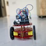
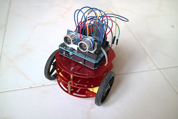
Assembling the Arduino robot to the platform
All the individual parts of the robot are now working. Next step is to connect everything to the robot platform.
Day 1: –
Day 2: What a difference! The Arduino shield made everything simple. I easily connected everything to the shield and it worked perfectly.
Programming the robot
After connecting everything, only one wheel was spinning. Since I had changed the code, I suspected I had introduced a bug somewhere. But I couldn’t find it!
I tried different things without any luck.
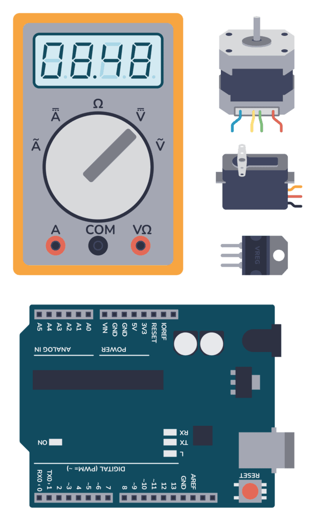
At last, I decided to go a bit more methodic at work. So I measured the voltages on the H-bridge module.
Everything was correct. Both motors had voltage. Still only one was spinning.
There was only one option left – the cables.
I changes the cables and voila! It worked!
We’ve had lots of problems with the cables while developing this robot. I suspect one of us had a bad batch of cables that was distributed among us.
At the end, I did not use the WiFi module. I found it more fun to try and make the robot move on its own. But I see at potential for making it semi-automatic. Adding maneuvers such as “attack”, “retreat”, “spin”, etc.
See the robot in action
Check out Part 2 of my VLOG from Colombia below to see me building and testing the robot:
Go back to the overview of Club de Arduino
More Arduino Tutorials
Basic Electronics for Arduino Makers
Learn the basics that every Arduino maker should know, and it'll open you up to a world of possibilities! Sign up for my circuit tips by email and I'll send you the eBook: