fbpx

The T Flip-Flop (Quickstart Tutorial)

The T Flip-Flop is a flip-flop that can toggle its output. Toggling means switching its output to its opposite; 1 becomes 0, and 0 becomes 1. This type of flip-flop is often used in counters and frequency dividers. In this quickstart tutorial, you will learn how it works, its truth table, and how to build

How To Use A Breadboard – The Beginner’s Guide

Resistor on a breadboard

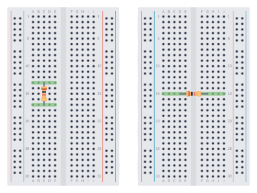
A breadboard is a simple and useful tool for connecting a circuit. It’s really useful for beginners as you can easily experiment and test out circuits without soldering. But it’s also useful for more experienced people since you can prototype an idea, or parts of a circuit, quickly.

I often use breadboards in my work.

Want a quick introduction to the breadboard? Check out my short video below (2:30) or continue reading.

Capacitors in Series

Capacitors in series

Capacitors in series are capacitors that are connected one after the other. The result always becomes a capacitance that is lower than the lowest value. In this guide, you’ll learn why this is the case and how to calculate their combined values. And I’ll also throw in a simple rule of thumb that you can

Capacitors in Parallel

How to connect capacitors in parallel

When you connect capacitors in parallel, you connect them alongside each other. And the result becomes a capacitance with a higher value. In this guide, you’ll learn why it works like that, how to calculate the resulting capacitance, and some examples of this in practice. As you’ll soon see, this is actually very simple. How

The JK Flip-Flop (Quickstart Tutorial)

JK flip flop symbol

The JK Flip-Flop is a type of flip-flop that can be set, reset, and toggled. It can be used for making counters, event detectors, frequency dividers, and much more. In this tutorial, you will learn how it works, its truth table, and how to build one with logic gates. What is a JK Flip-Flop? Flip-flops

The D Flip-Flop (Quickstart Tutorial)

A basic D flip-flop

The D Flip Flop is an edge-triggered circuit that combines a pair of D latches to store one bit. It is commonly used as a basic building block in digital electronics to create counters or memory blocks such as shift registers. In this tutorial, you will learn how it works, its truth table, and how to build one with logic gates.

The D Latch (Quickstart Tutorial)

The D Latch is a logic circuit most frequently used for storing data in digital systems. It is based on the S-R latch, but it doesn’t have an “undefined” or “invalid” state problem. In this tutorial, you will learn how it works, its truth table, and how to build one with logic gates.

Full Adder Circuit – How it Works

A Full Adder is a digital circuit that performs the addition of three binary inputs. In this tutorial, you will learn how this circuit works, its truth table, and how to implement one using logic gates.

Schematic for a Full Adder Circuit
A Full Adder Circuit

What is a Full Adder?

Adders can either be Half Adders or Full Adders. The difference is that the Half Adder is used to add only two 1-bit binary numbers, therefore its sum can only range from 0 to 2. To improve this performance, the Full Adder was developed. It is able to add three 1-bit binary numbers, achieving a sum range from 0 to 3, which can be expressed with two output bits (“11”). 

The S-R Latch (Quickstart Tutorial)

The S-R latch is a key circuit in digital storage units. In this tutorial, you will learn how it works, its truth table, and how to build one with different logic gates.

S-R Latch Symbol
S-R Latch Symbol

What is an S-R Latch?

Before starting with the S-R latch you need to know what a latch is. A latch is an asynchronous circuit (it doesn’t require a clock signal to work), and it has two stable states, HIGH (“1”) and LOW (“0”), that can be used for storing binary data. Many sequential circuits and larger storage devices, such as shift registers, use latches as their principal building block.

The Useless Halloween Machine

Drawing of useless machine circuit soldered

This year’s Halloween project is a useless machine built with 555 timers. It’s a coffin with a switch. When you flip it off, a dark force rises from the coffin and flips it back on. This project uses two 555 timers to control the position of a servo motor, which was a fun challenge in itself.

Check out the video below to see the result:

Half Adder Circuit – How it Works

Half adder circuit

A Half Adder is a digital circuit that adds binary numbers. In this tutorial, you will learn how it works, its truth table, and how to implement one using logic gates. 

Half Adder Circuit
A Half Adder Circuit

What is a Half Adder?

A Half Adder is a digital circuit that carries out the addition of binary numbers. It’s the simplest of digital adders and you can build one using only two logic gates; an XOR gate and an AND gate.

How to adjust the brightness of an LED

Do you want to adjust the brightness of your Light-Emitting Diode (LED)? If we break it down to the most basic, there are two ways to change the brightness of an LED:

  • Changing the resistance value.
  • Turning it on and off fast (Using PWM).

Below I’ll explain the two options and show you circuits you can build.

Arduino Shield Project LED matrix

How to Build a Touch Sensor Circuit

Touch LED Circuit protoboard

In this project, you will build a touch sensor circuit. It’s a cool and simple circuit that allows you to control an LED with the touch of a finger. And you only need three components, how cool right? You can build this circuit if you’re a total beginner. The Touch Sensor Circuit Diagram You only

Voltage Divider Tutorial For Beginners

The basic voltage divider circuit

A voltage divider is a circuit that creates a smaller voltage from an input voltage by using two resistors. You’ll see it in both simple and advanced circuits all the time. Here’s the basic setup:

The basic voltage divider circuit

It is useful for example for reading sensors like thermistors and photoresistors since it converts an unknown resistance into a voltage. Or to reduce the volume of an audio signal via a potentiometer.

You can find the output voltage by inserting the resistor values and the input voltage into the following formula:

V_{OUT} = \frac{R2}{R1+R2} \cdot V_{IN}

Or you can use the calculator a little bit further down on this page.

Once you know how it works, it’s much easier to see how circuits work. And it will let you calculate voltages at many different points in a circuit – which is often needed to understand it.

NOT Gate (Inverter) – Logic Gates Tutorial

NOT gate truth table and symbol

A NOT gate (or inverter) is a logic gate where the output is the opposite of the input. So you can say that the output is NOT the same as the input. It’s often called an inverter since it inverts the input. The schematic symbol for an inverter is like a buffer, just with a