fbpx

Understanding Basic Electronics is Easy

Some basic electronic components drawn as cartoons

Yes, basic electronics is easy. As long as you don’t make it complicated (which many unfortunately do).

An electrical current is the flow of electrons in a wire. Electrons flow when you have a “closed loop” – a path from the negative to the positive terminal of a battery.

Basic electronics - current flow

For example, if you connect a small light bulb to the positive and the negative side of a battery, you will get a closed loop where electrons can flow and make the lamp shine.

“Electronics” control electrical currents by combining different components.

What is Basic Electronics?

Many think that basic electronics has to do with the physics of how electrons move. But that’s particle physics, not electronics!

You can learn the basics of electronics by learning this:

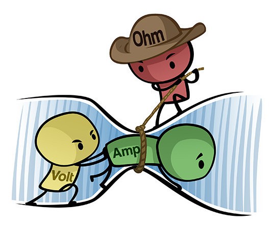
  • The basics of current and voltage
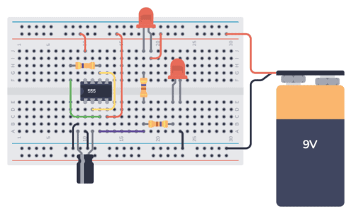
  • How the most common basic components work
  • How electronic schematics work
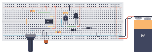
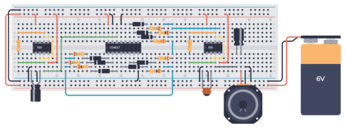
  • How to build circuits from schematics
Ohms law cartoon

555 Timer TV Remote Jammer – Complete Instructions

Here is a nifty little circuit that’s designed to make sure nobody messes with your TV settings while you are watching your favorite show – a 555 timer TV remote jammer! This sneaky device sends out an invisible signal at a frequency that the TV thinks is coming from a remote control. But instead of

555 Timer Music Box – a Synthesizer with 10-Tone Sequencer

This is a fun project to build – a 555 Timer music box! It’s based on two 555 timers, one that sets the tempo of the music, and one that creates the different tones. The sequence of which tones to play is managed by a decade counter IC and some resistors. The Circuit You can

555 Timer Railroad Lights

This is a 555 Timer railroad lights project where two lights are alternating, similar to a railroad crossing signal. The 555 timer is set up in astable mode so that it keeps switching its output between HIGH and LOW, thereby turning on and off the two LEDs connected to the output. The Circuit To build

555 Timer Machine Gun Sound Effect

This 555 Timer machine gun circuit generates a sound that mimics the sound of a machine gun. It is based on a 555 timer IC, which is a popular chip used for creating pulses and timing circuits. The Circuit To build this circuit you’ll need a 555 timer, a speaker, a few capacitors, and a

A Simple Guide to RGB LEDs

RGB LEDs are a type of LED that can emit a wide array of colors. In this tutorial, you’ll learn how RGB LEDs work and how to use them with Arduino or in other circuits to produce different colors.

RGB Leds gift

A Light-Emitting Diode (LED) is a small component that illuminates when current flows through it. RGB LEDs operate on the same principle, but they internally contain three LEDs (Red, Green, and Blue) capable of combining to produce nearly any color output.

Arduino IR Transmitter Circuit and Code Example

Arduino IR Transmitter circuit

In this guide, you’ll learn how to set up an Arduino IR Transmitter circuit. It lets you control an IR (Infrared) LED and send any remote control code from your Arduino. This means you can use it to control your TV or anything else you feel like! This tutorial focuses on just setting up an

555 Timer Metronome Circuit

The 555 timer IC is a versatile component that can be used in various circuits, including a metronome. A metronome is a device used by musicians to keep a steady tempo during practice. In this tutorial, you’ll learn how to build a simple metronome using the 555 timer IC. Parts List The Circuit The 555

How Rotary Encoders Work

How rotary encoders work

Rotary encoders are components used for measuring the rotation of a shaft or axle. They are often used for volume knobs in audio equipment, DIY gaming controllers, or as an input device for different Arduino or Raspberry Pi projects. In this guide, you’ll learn how rotary encoders work and how they can be integrated into

Arduino Rotary Encoder: Tutorial With Example

In this tutorial, you’ll learn how to interface an incremental rotary encoder with an Arduino to read the movement of the knob. This can be useful for creating user interfaces or reading mechanical positions in robotics and other applications. What You Will Need Schematic and Breadboard Setup Note that in this schematic I’m using a

Arduino Motor Guide: How to Drive a DC Motor

DC Motor illustration

In this Arduino motor guide, you’ll learn how to drive and control the speed of a DC motor using an Arduino UNO and a TIP120 transistor. In this example, you’ll use a pushbutton to ramp up the motor speed and then slow it down, thanks to the power of Pulse Width Modulation (PWM). Materials Needed:

Arduino Servo Motor: Reference Code and Wiring Example

In this Arduino servo motor tutorial, you’ll learn how to control a servo motor using an Arduino UNO board and a potentiometer. As soon as you’ve got this example project up and running, you’ll have the skill of controlling servo motors from your Arduino. This can be the basis for more advanced robotics projects. Components

Arduino Hall Effect Sensor: How to Detect Magnetic Fields

In this guide, you’ll learn how to set up an Arduino Hall effect sensor, specifically the US1881, to detect magnetic fields. This can be useful for projects where you need to find the RPM of a motor or other movements in a machine. Parts Needed Schematic Diagram Connect the VDD pin of the US1881 Hall

Arduino Ultrasonic: Controlling an HC-SR04 with Arduino UNO

A popular Arduino Ultrasonic Sensor is the HC-SR04. It’s widely used for non-contact distance measurements and often used in robotics and automation projects. This guide will show you how to connect an HC-SR04 to an Arduino and write a simple program to measure distance. Requirements Connection Diagram Step-by-Step Guide Arduino Ultrasonic Example Code Copy and

What Is A Resistor And What Does It Do?

A resistor on a breadboard

The resistor is a component that resists the flow of current. It doesn’t do anything actively, so it’s called a passive component. Sounds boring and pretty useless, but it’s actually an extremely useful component. Once you know the basics of the resistor – and how it works with currents and voltages in a circuit –