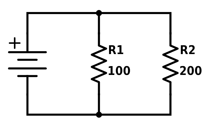
A circuit simulator is a tool for “seeing” what a circuit does. In comparison to mechanical machines such as a bicycle and a lever, electronics cannot be easily inspected by the naked eye.
When you look at a bicycle you can observe it and see that stepping on the pedals makes a chain turn, and that this chain moves the bicycle wheels.
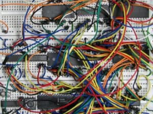
In contrast, if you open up an audio amplifier, it will be really hard to tell what it does if you don’t have previous experience in designing and building electronic circuits.


 A short circuit is a connection that was not meant to be there. For example, if you accidentally connect the plus to the minus of a battery, you have a short circuit between the plus and minus of the battery. Which is not good.