One of the things that I love about being able to build electronics is that I can also REPAIR electronics =)
I often get the question:
“How can I learn to repair electronics?”
My response is:
One of the things that I love about being able to build electronics is that I can also REPAIR electronics =)
I often get the question:
“How can I learn to repair electronics?”
My response is:
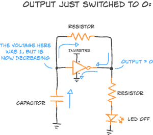
Below you can see the circuit we’re currently talking about.
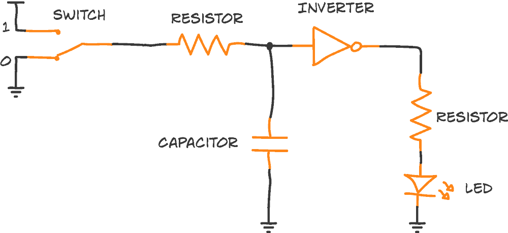
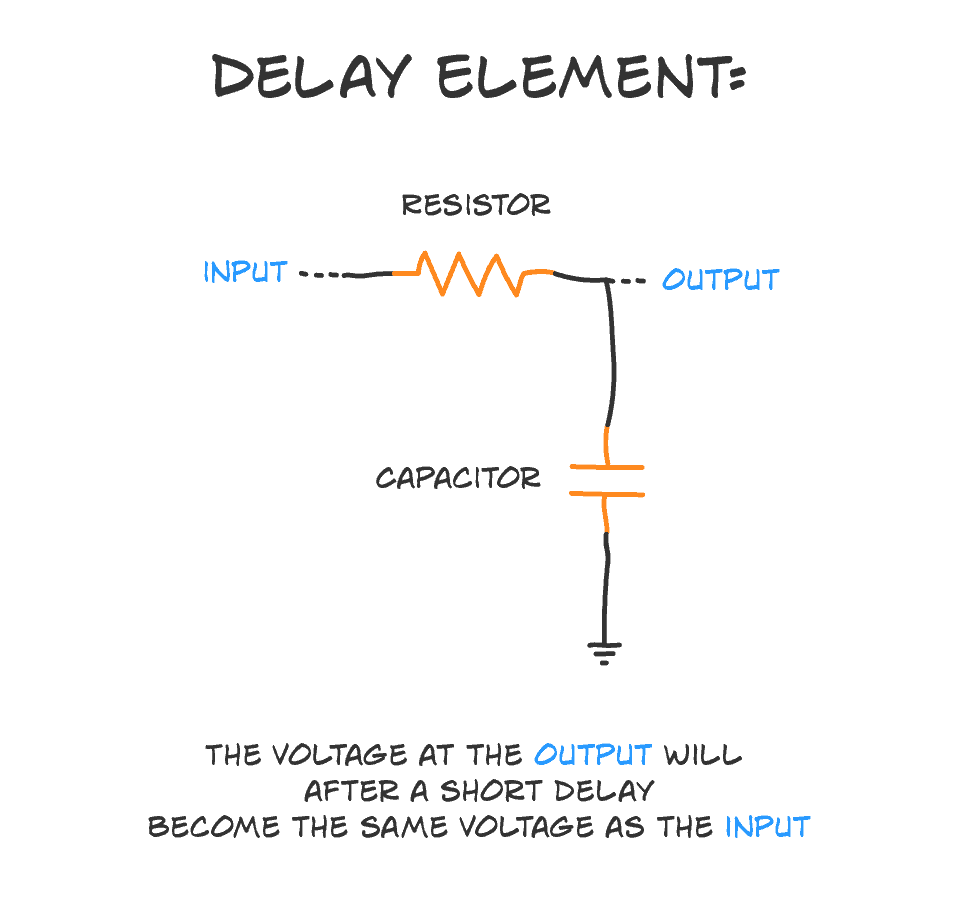
The resistor and capacitor on the left of the inverter make up an RC delay element:
But how does the current flow in this circuit?
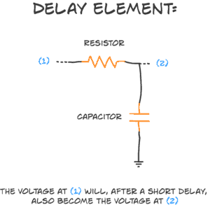
The RC delay element is a way to create a time delay in your circuit by connecting a resistor and a capacitor. It’s super simple. And very useful.
The ‘R’ is a resistor, and the ‘C’ is a capacitor. That’s where the ‘RC’ comes from. And here’s how you connect the two:
Thomas was right. It was impossible to get anyone to do anything in December in Medellin. So I continued on my own.
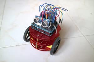
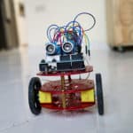
There was one challenge left before I could assemble it all and program the robot: The ultrasonic sensor.
I hadn’t tested it yet, so I had no idea how well it would work.
I remember something I struggled with in the beginning.
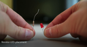
The LED.
It’s supposed to have a fixed voltage drop, right?
Like 2V.
But what if I force 3V across its legs with a 3V battery?


This week we got a new member. So we revised what we’ve done so far with our new member:
The first week we looked at different robot platforms. We wanted to be able to go forward, backward, and make turns. And we wanted it as cheap as possible. We looked at different platforms at the local store, then settled for one with three wheels, three levels and two motors.
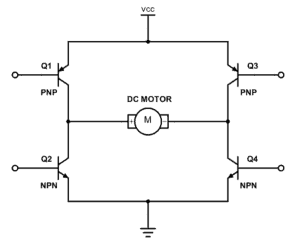
An H-bridge is a simple circuit that lets you control a DC motor to go backward or forward.
You normally use it with a microcontroller, such as an Arduino, to control motors.
When you can control two motors to go either forward or backward – you can build yourself a robot!

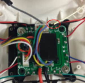
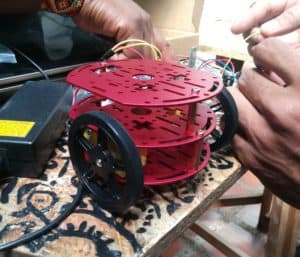 We made progress on our robot this week! Check out the video at the end of this post.
This is what happened:
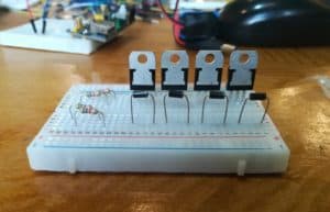
During this week I figured out that our H-bridge circuit did not work as intended.
The problem was the TIP12x transistors. They have a huge voltage drop from collector to emitter of 2V. With two of them in the H-bridge design, there was only 1V left for the motor.
I thought the problem was the design. That we needed to increase the current or something to reduce the voltage, but I was unable to do it.

We started out as a group of three people.
Eduardo, Jefferson, and me.
Today, we discussed what to build.
We wanted to build something that would be fun, and that we could finish within the time frame I’m going to stay here (~2 months).
And it should be based on an Arduino.
Jefferson wanted to build a CNC mill.
But such a machine is a bit complex, so we decided to discard that for now.
Then Eduardo suggested building a sumo robot.

It was sunny and hot.
I was wearing a backpack and I could feel the sweat building up on my back.
But I had to walk fast.
Because I was late.
And because the locals had told me to be careful in the center.
I had emailed with Thomas, the founder of the makerspace Göra, before coming here.
We had discussed electronics workshops but decided that it would be better to meet in person to figure out the details.
I did not know what to expect.
Across the street, I saw it.
Nooooo!
It is not.
It’s a common misunderstanding.
But let me make it clear:
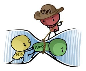
The current after a resistor is the exact same as it was before the resistor.
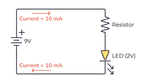
“But doesn’t the resistor reduce the current?”
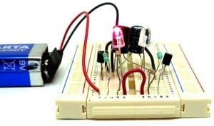
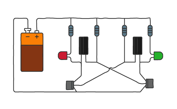
The astable multivibrator circuit is a classic circuit for flashing two LEDs. It doesn’t have to flash two LEDs though. It can blink just one LED. Or it can create a tone to play on a speaker.
First, let me show you the circuit in action:
Want to know the theory behind how the circuit works?
There have been many attempts to explain this circuit. Most have failed to explain it to other than those already beyond the beginner level.
So here’s my humble attempt.
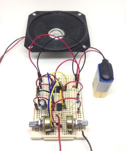
Do you want a fun and easy-to-build circuit? Here’s the simple, but fun Atari Punk Console – with schematics and parts list. It’s a quick build, so you can easily build it during an evening.
It takes its name from the old Atari computers of the 80s because it makes similar sounds.
And after my (not-so-intense) research (I basically just read about it on Wikipedia), I’ve come to learn that the circuit was first published in a Radioshack magazine in 1980.
Here’s a short clip of me playing with the circuit I built:

“We’re never going to make it!”
Jensa and I arrived early at the airport in Oslo.
But that didn’t help. Because our flight from Oslo had technical problems. So it was delayed and we missed our connecting flight to Hong Kong…
Not a good start of our trip…