fbpx

Arduino RGB LED Guide: Easy Setup and Code Examples

Arduino RGB LED on a breadboard

In this guide, you’ll learn how to control an RGB LED using the Arduino. An RGB (Red-Green-Blue) LED can produce a wide variety of colors by mixing different intensities of red, green, and blue light. You’ll learn to create a basic Arduino RGB LED circuit and cycle through some basic colors as an example.

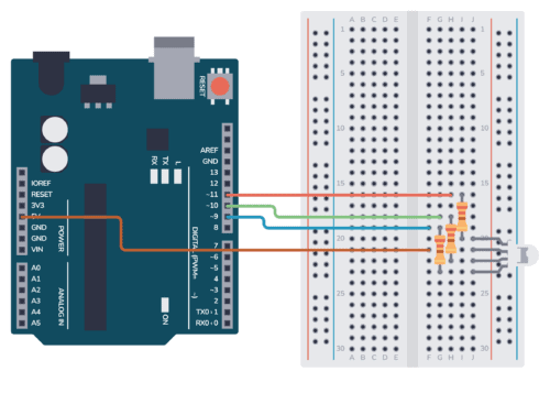
Using the provided schematic and breadboard images, as well as the example code below, you should have everything you need to easily set up and control an RGB LED’s color output on your own.

Parts Needed

There are two types of RGB LEDs: Common Anode and Common Cathode. We’ll provide example schematics and code for both types below.

Arduino Thermistor Guide: Easy Circuit & Code Walkthrough

Arduino thermistor circuit

In this tutorial, we’ll guide you on how to set up a thermistor with Arduino to create a basic thermometer. The schematic, breadboard illustration, and example code provided will make it easy and straightforward to get your thermistor working.

Parts Needed

Step 1: Understand the Thermistor

Our thermistor has the following parameters:

Arduino Light Sensor – Circuit and Code Example

Arduino Light Sensor Circuit

This Arduino Light sensor circuit is a simple example that shows you how to connect light sensors such as photoresistors, photodiodes, and phototransistors, to an Arduino.

In this quickstart guide, you’ll learn how to connect a photoresistor to an Arduino board and read out the voltage. You’ll first use the Serial Monitor to learn about how the light sensor behaves, then you build a circuit that automatically turns on a light when it gets dark.

This is a great practice circuit when you’re learning Arduino. The code is straightforward and the light sensor connections are simple.

Parts Needed

* A photodiode or phototransistor will also work.

Arduino Button – Circuit and Code Example

Arduino button circuit on a breadboard

This Arduino button circuit is a simple example that shows you how to connect buttons to an Arduino.

In this quickstart guide, you’ll learn how to connect a button to an Arduino board and read a HIGH or LOW depending if the button has been pushed or not. You’ll use the Light-Emitting Diode (LED) that is included on the board to turn on and off with the button so that you can verify that your button press code is working properly.

This is a great practice circuit to build as you’re learning Arduino. The code is straightforward and the connections are simple.

Parts Needed

  • Arduino Uno
  • Breadboard (and some breadboard wires)
  • Resistor 10 kΩ (R1)
  • Resistor 470 Ω (R2)
  • Pushbutton or Switch
  • Wires

Arduino Button Circuit

To connect a button to an Arduino, you’ll need a pull-down or a pull-up resistor. This is to make sure that when the button is not pushed, it has a defined value. In this example, we’re using a pull-down resistor of 10 kΩ.