fbpx

Binary Number System And Working With Ones And Zeroes

Binary number system - ones and zeroes

The binary number system is an important system in digital electronics. Because in digital electronics we are using only 1’s and 0’s. But what does this mean?

That’s something I was wondering about for a long time. I thought it was something really difficult and abstract. But when I one day asked my dad about it, it really surprised me how easy it was!

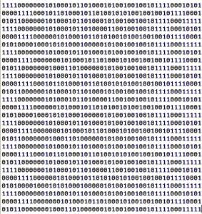
It turns out that a “1” is just a wire with voltage and a “0” is a wire without a voltage. It’s that simple!

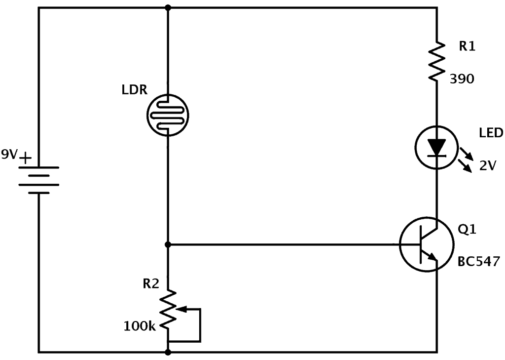
The reason for this system is to make the electronics easier. A circuit which only needs to check if there is a voltage or not on the wire is really easy. Just have a look at how the transistor works and you’ll get an idea.

In order to make any sense out of the ones and zeroes, we use a binary number system.

Circuit Diagram: How To Read And Understand Any Schematic

Circuit design from scratch

When you start learning about electronics, you might see a circuit diagram drawn with realistic looking drawings of the different components.

But this method is not very effective.

To make them more effective, all electronic components have been assigned much simpler symbols. And wires are drawn as lines to show how to connect them.

It’s not always easy to understand a circuit diagram. But with practice and experience you will understand more and more.

Capacitor Values – Prefixes, Standards and Calculations

There are some standard capacitor values that have developed over time. To find the value you need for your circuit you need to know how to deal with prefixes. And you need to know how to calculate capacitor values.

Electrolytic capacitor

If you have looked for capacitors, you have probably seen many different letters and weird values. Like 0.47 µF or 22 pF. It is a bit confusing, but it’s easy to learn what it means.

In this article you will learn the most standard capacitor values, the prefixes used and how to calculate a capacitor value for your circuit.

Build A Circuit Efficiently With 5 Techniques

Microcontroller circuit board

Have you ever had those times where you were really passionate about a project? But somehow you never found the time to continue on it. And before you knew it weeks turned into months and you decided to give up on it… I hate that feeling! Learn the tricks to build a circuit efficiently.

Build a circuit

I can remember several times when I have been in that situation.

  • Do you have a project you have been wanting to work on for a long time?
  • Do you always find yourself too busy to work on it?
  • Do you wish there was a way to spend more time on your project without cutting down on other activities that you appreciate doing?

This is completely normal. I get hundreds of emails every month, many from someone who wants to build a circuit, but can’t because he is too busy.

But what I have found through my own experience and through communicating with people like you is that it’s not about not having enough time.

DIY Sous Vide Cooker

This DIY sous vide cooker was made by my friend Markus. He built it for about 1/10 of the price of the commercial cookers. And it made some really good chicken =)

A sous vide cooker is a machine for cooking food using a temperature-controlled bath.

You can take whatever you want to cook – chicken, fish, steak, etc. – and put it in a vacuum-sealed bag. Next, set the temperature on the DIY Sous Vide to the temperature you want for your food. Then put the vacuum-sealed bag into the water and let it cook slowly for a long time (several hours).

When the chicken (or whatever you are cooking) is done, fry it quickly in a frying pan with high temperature to get a crispy finish.

How To Make Circuits On A Stripboard

A stripboard is a circuit board with holes and printed strips of metal.

Stripboard circuit with components

These boards are a good way of connecting simple to medium complicated circuits. I highly recommend using stripboards in the beginning. They give you a lot of control of your connections and it’s relatively easy to fix errors.

Though when your circuit gets too many connections, it can be a real hassle keeping control of all the connections.

Digital Stopwatch Circuit

This digital stopwatch circuit is a circuit I built for testing some 7-segment displays. It consists of four displays that I control using a microcontroller. The microcontroller counts and makes sure the correct LED segments on each display is lit up.

Check out the video below to see how I built it.

How To Build Circuits

Build Circuits Using a Stripboard

If you want to make electronics you need to build circuits. But how to build circuits?

Here are three methods you can use to build any kind of circuit, ranging from super simple to advanced.

Build Circuits With A Breadboard

Breadboard with blinking LED circuit

Building circuits using a breadboard is super easy and quick.

A breadboard is a board for prototyping. It has holes where you can stick component leads or wires into. Some of the holes are connected horizontally and some are connected vertically.

The Protostack Development Kit

Today I checked out the Protostack Development Kit. This is a board that comes with an AVR microcontroller and the necessary components to get the microcontroller up and running.

Basically, that means it comes with a voltage regulator, some capacitors, an LED, a power connector, and a connector for an ISP programmer.

You can find the board here

Using Your Soldering Iron In Another Country

Have you ever considered bringing your soldering iron on vacation?

I am in Mexico at the moment and of course I have my soldering iron in my suitcase. But here the other day I got myself a surprise that I never considered could be a problem.

ERSA-30 Soldering Iron

I have an old ERSA-30 soldering iron that I inherited from my dad. It’s designed for the European 220V wall plug. Therefore I used an adapter to make it fit the Mexican wall plug. It’s not a converter, just a simple mechanical adapter that lets me plug my European plugs into the Mexican plugs.

I wanted to solder some stuff, so I plugged it in and waited…

Arduino Remote Control Tutorial

In this tutorial, I am going to show you exactly how to make an Arduino remote control. You can use this project to combine functions from different remote controls and make your super-awesome dream remote control!

IR diode connected to Arduino

If you are not familiar with Arduino, check out What is Arduino and Where to start?

A remote control sends out an infrared (IR) code when you push a button. The gadget you point the remote control at will receive this IR code. To make your own Arduino remote control, you need to first copy the IR code from an existing remote control using an IR receiver.

To create our remote control we need to:

  • Get the button code from the original remote
  • Make a remote-control program
  • Upload our program to the Arduino

We will use these components for our Arduino project:

Make A Plastic Project Box

A plastic project box is nice to have to make your project look better. This has always been one of my weaknesses. I can make a really advanced circuit, but when it comes to package it, I have some kind of disability.

ADBO - Plastic Project Box for Arduino (laser cut)

Luckily there are some tools out there for people like me.

Here are three methods of making a plastic project box for you circuit:

  • 3D Printing
  • Laser Cutting
  • Modify Standard Boxes

USB Circuit Development Made Easy

Using a USB circuit is the most common method for communicating between devices and computers.

USB plug

In the old days usually people used the parallel port or the serial port. But these ports are becoming more and more rare. And on laptops they are almost non-existent.

But all computers have USB ports.

Yeah, and USB stands for Universal Serial Bus just in case you didn’t know ;)

LDR Circuit Diagram

This LDR circuit diagram shows how you can make a light detector. An LDR or “Light Dependent Resistor” is a resistor where the resistance decreases with the strength of the light.

Here is the schematic for the circuit:


LDR Circuit Diagram