
SexyCyborg is an electronics geek out of the ordinary. And I love to see people being different than the norm, especially in the hobby electronics world.
So, I knew I had to interview her.

SexyCyborg is an electronics geek out of the ordinary. And I love to see people being different than the norm, especially in the hobby electronics world.
So, I knew I had to interview her.
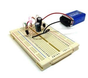
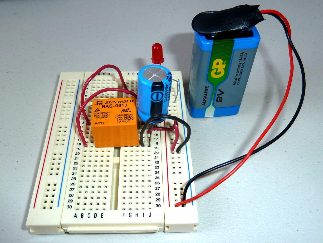 I really like the circuit that blinks a light with a relay.
Like this:
If you connect a battery to the electromagnet of a relay, through its normally closed contact, you will get a relay that switches on and off really fast.
If you add a big capacitor (like 1000 µF) over the electromagnet, the electromagnet will stay on longer.

Check out this simple tip that Michael sent me:
[MICHAEL]:
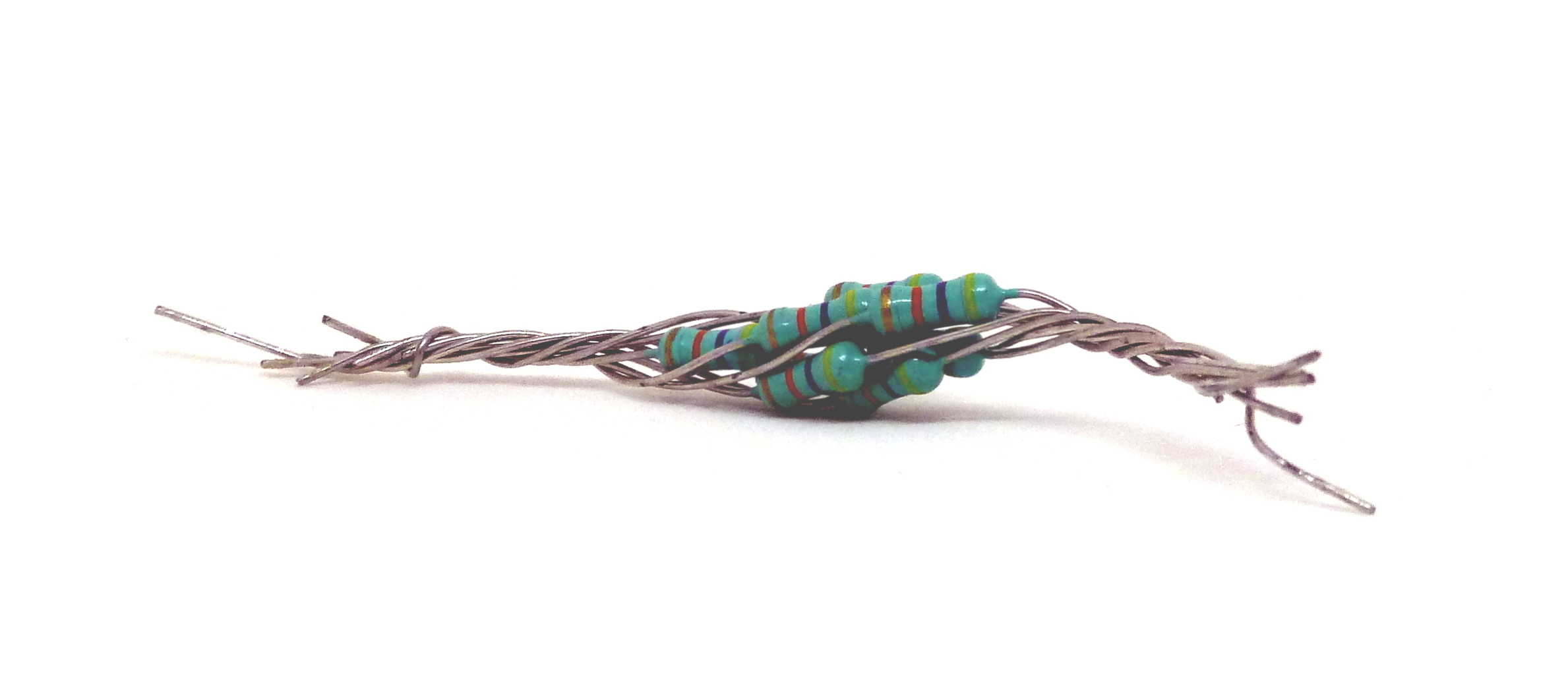
“I was making a small practice audio amplifier and was in need of a 2.5 Ohm resistor. I didn’t
have one and didn’t want to wait for an order to be fulfilled.

 I’ve done some research.
A couple of weeks ago Tek.no, a Norwegian tech-magazine, asked me if I could write an article for them.
There are a lot of people online claiming they have fixed broken graphic cards and other hardware, by baking it in an oven.
Are you doing this?
Don’t worry, I’ve done all of these mistakes myself.
And sometimes it works.
But by learning the correct soldering technique, you reduce the chances of mistakes in your circuit caused by a bad solder joint.
1. Removing iron before applying solder
When I teach someone how to solder, I usually say that you should first heat the pin and the pad, then apply the solder.
But sometimes my explanation isn’t clear enough. I’ve seen students heating the pad and the pin, then removing the soldering iron before trying to apply the solder.
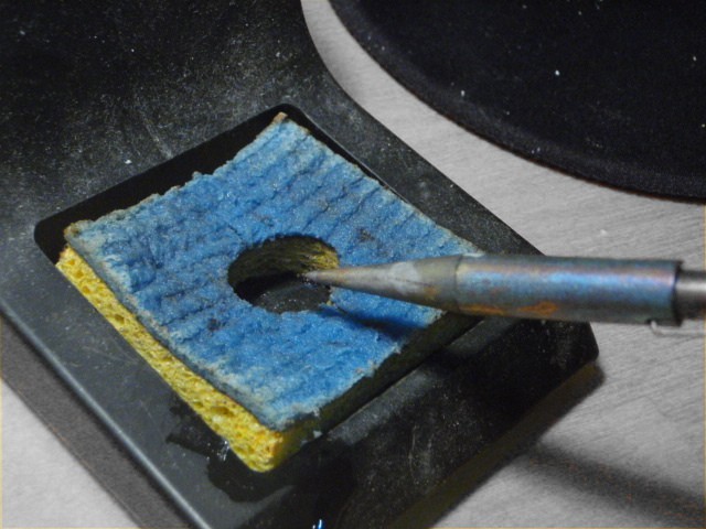 The right soldering temperature is something many don’t really think about.
But, have you ever used one of those soldering irons with a variable temperature setting?
If you have, you might be wondering the same thing as Jyri. Jyri wrote to me in an email about soldering and asked: “I always wondered – what is the right soldering temperature in various situations?”
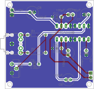
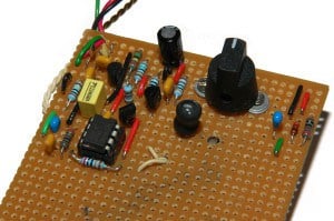
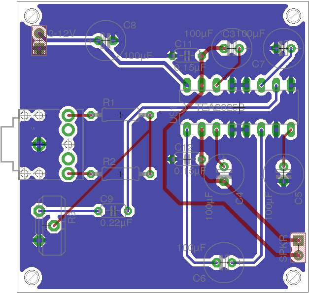 This is the easiest mono amplifier circuit to build, as far as I know.
I love it because it is powerful enough to play pretty loud. And it doesn’t need a pre-amp, heat-sink or any weird transistors.
All it requires, is a few standard capacitors, a couple of resistors and a potentiometer.
It will give you 4.7 Watts of power. This should be enough to play music in the park with some friends and a couple of brewskies.
I’ve added the schematics, PCB design and Gerber files a little further down the page.
“What can you build with electronics?”, she asked me…
“Anything!” I said.
She looked at me with a blank stare. Apparently that was not a satisfying reply.
This happened to me a few days ago.
Sometimes I get too deep into electronics that I forget “normal” people don’t necessarily understand what you can do with electronics.
So…
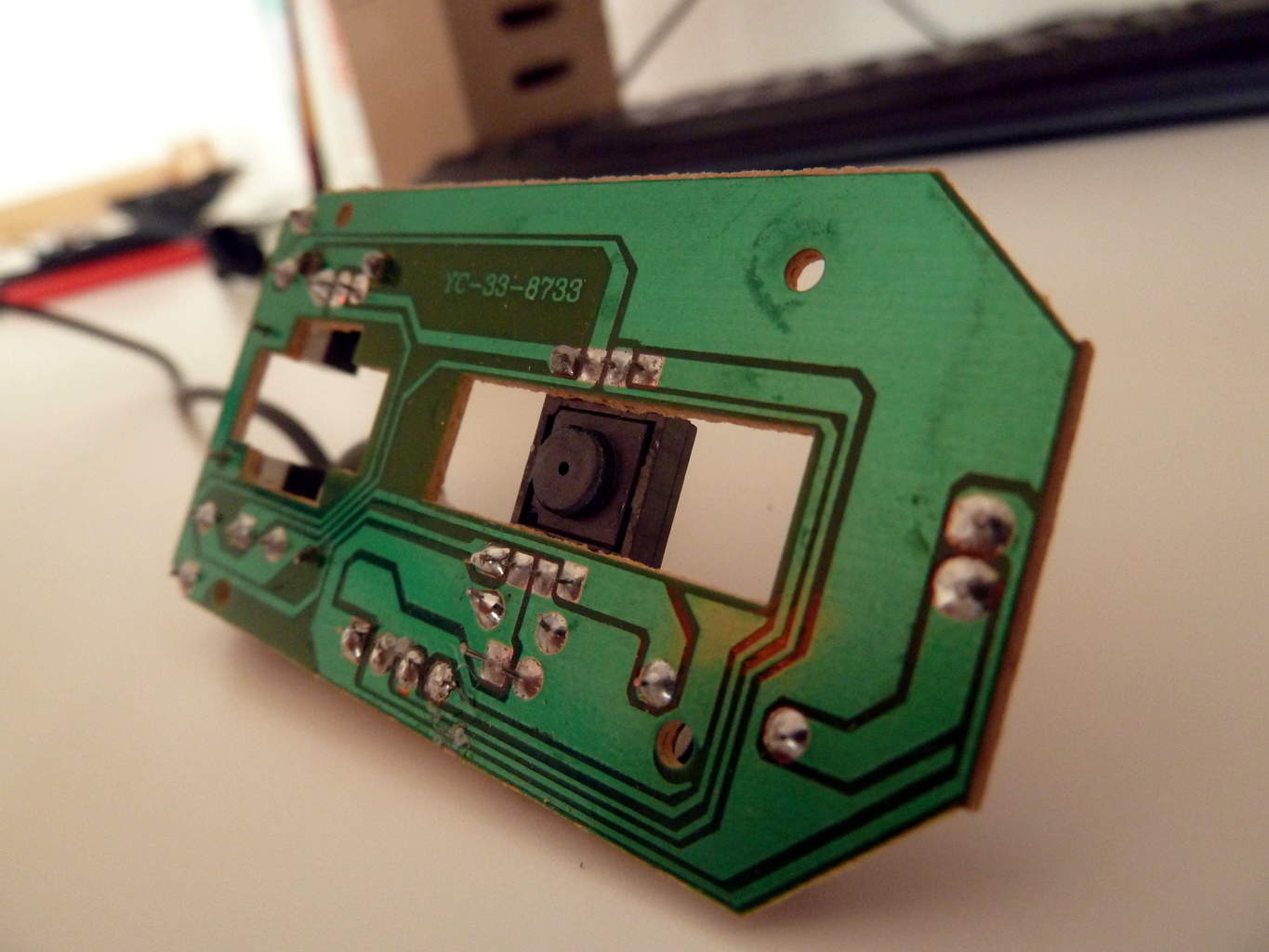
Can you get money for your old circuit boards?
Apparently yes…
Anne Staley wrote to me a while back.
She was very enthusiastic about the environment and recycling. And she asked me if she could write an article on my blog about this.
I answered that it probably wasn’t something for my blog.
But she persisted. And she wrote the article and sent me. And as I read through it, I realized that it could be an interesting thing to learn about. Even as a hobbyist.
It turns out that you can actually earn money on your old circuit boards. Circuit board recycling sounds like a good idea =)
Read the article below:
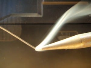
 «It went through the circuit board, like a knife through warm butter.»
This could have been the intro to an incredibly capturing novel about through-hole components. But it’s not. I don’t think anyone has made a novel about such a narrow topic.
Oh, wait! I had to do an Amazon search after writing that. Turns out this one is something close. But something tells me it won’t start like my example-intro.

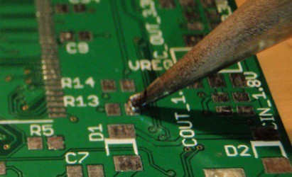
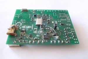
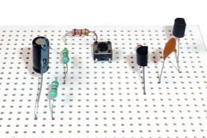
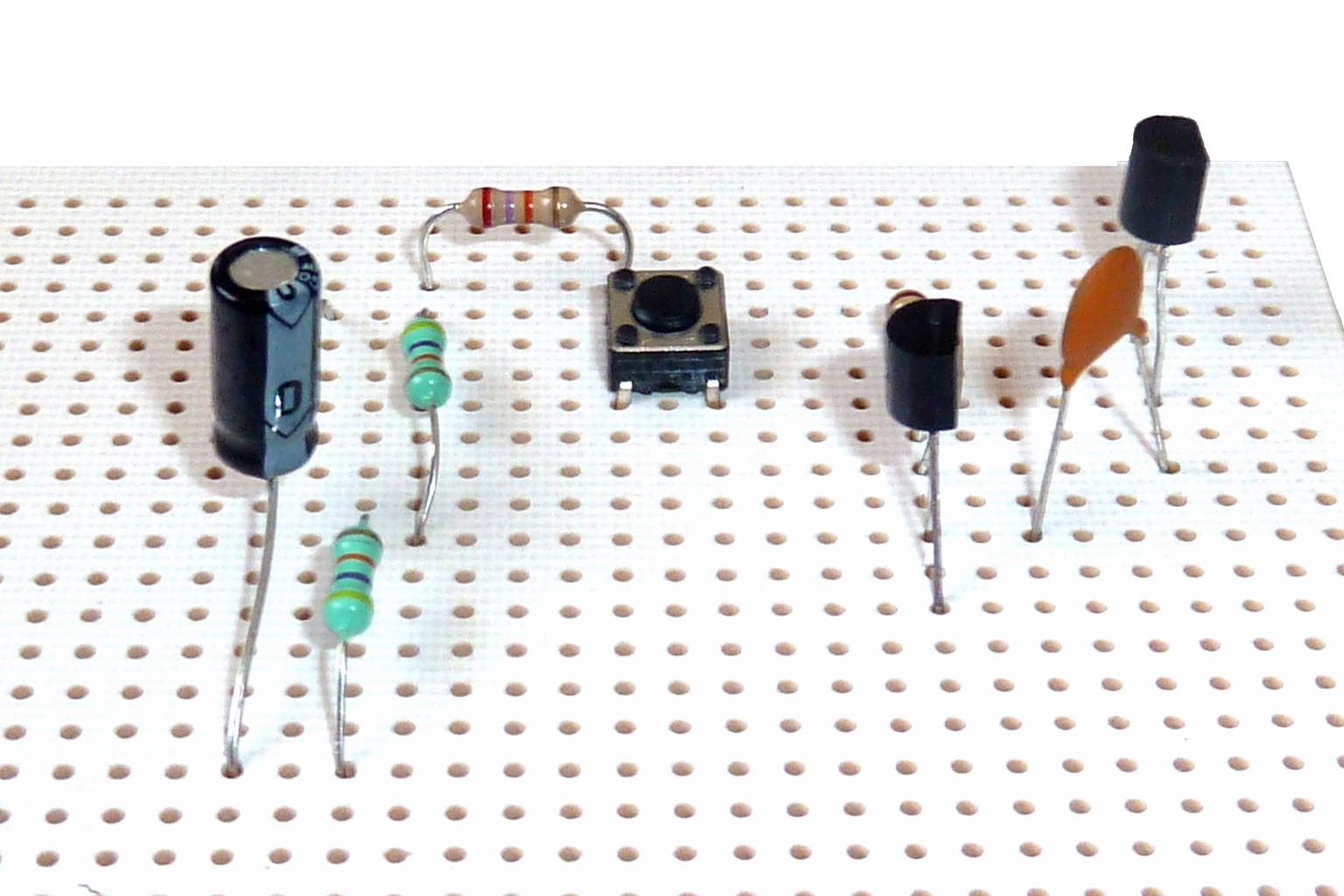
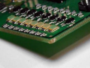 SMD components are small and kind of scary if you have never used them before. And the first time you want to solder one – you will probably start to doubt if you’re actually able to do it.
Even though I have soldered many SMD components, I still get that “Oh man, that component looks tiny!”-feeling. But usually, it works out fine. As long as it’s not too small.
SMD is short for surface-mount device. I always get a bit confused about the terminology, but I think SMD describes a printed circuit board, with components that are mounted on the surface of the board. So an SMD component is actually a surface-mount device component.

Every Christmas I turn into a child again.
I have a hard time falling asleep. I wake up early in the morning to watch cartoons. And I am probably even more curious about the gifts under the tree than my two-year-old nephew.
I often get emails asking for project ideas.
So I thought I’d share a few Christmas circuit ideas today.

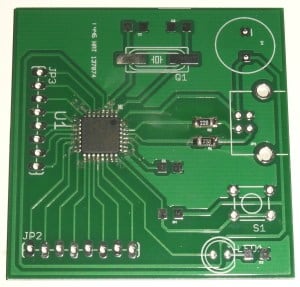
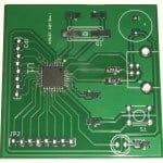
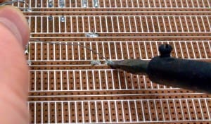
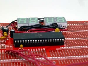
Oh man! When I made my first printed circuit board, I was so thrilled!
It was extremely satisfying to be able to touch my own circuit board design. And today it’s time you learn it too.
And the truth is that the process isn’t that hard. There are just a few steps you need to go through. And anyone can do it – even if you have no experience from before.
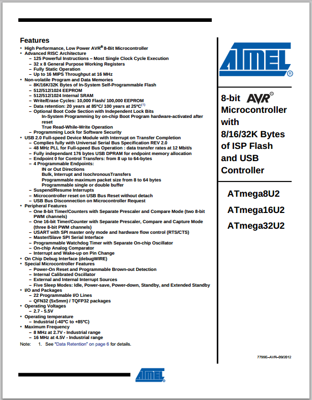 I was sitting in front of my computer. It was the first time ever, that I was looking at a datasheet. I didn’t understand anything. This was too hard. So I closed it.
But I tried again and again. And little by little, I started to get familiar with the information in the datasheet. And it was actually really exciting!
If you are a beginner, you might have experienced the same. The datasheet looks really complicated – and you just want to close it right away.
However, when you learn what to look for, the datasheet soon becomes your best friend.
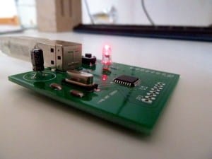

To complete today’s part of the microcontroller tutorial – I have doubted myself, I’ve burned my finger and I’ve received a surprise bill from the customs.
But all in all, I’m very happy with the result. I made it work. And I love the feeling I get when I make something work!
We are now at part 5, the final part, of the microcontroller tutorial. Up until now we have learned: