The astable multivibrator circuit is a classic circuit for flashing two LEDs. It doesn’t have to flash two LEDs though. It can blink just one LED. Or it can create a tone to play on a speaker.
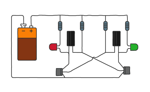
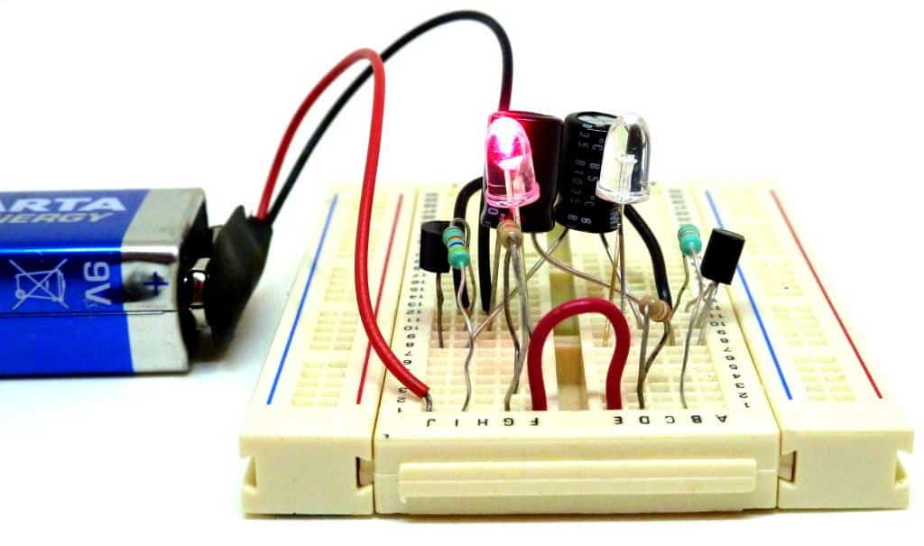
First, let me show you the circuit in action:
Want to know the theory behind how the circuit works?
There have been many attempts to explain this circuit. Most have failed to explain it to other than those already beyond the beginner level.
So here’s my humble attempt.
But let’s keep this interactive – ask me about the things you don’t understand in the comments section at the bottom. And I’ll update the article as I discover what is missing.
The Astable Multivibrator Circuit Diagram
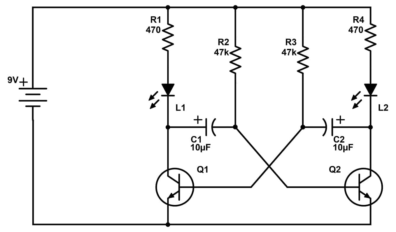
This is a classic oscillator circuit.
The Light-Emitting Diode (LED) on the left side is lit when the transistor on the left side (Q1) is ON. The LED on the right side is lit when the transistor on the right side (Q2) is ON.

10 Simple Steps to Learn Electronics
Electronics is easy when you know what to focus on and what to ignore. Learn what "the basics" really is and how to learn it fast.
Resistors R1 and R4 are only there to set the current through the LEDs.
Which means the remaining six components make up the oscillator: Q1, Q2, C1, C2, R2, and R3.
Understanding the Astable Multivibrator
The voltage on the left side of C2 controls transistor Q1.
The voltage on the right side of C1 controls transistor Q2.
When transistor Q1 turns ON, it changes the voltage of C1 so that Q2 turns off.
After a short while, the voltage of C1 rises back up and turns on the transistor Q2.
When transistor Q2 turns on, it changes the voltage of C2 so that Q1 turns off.
This keeps repeating.
But that’s a very superficial explanation.
What if you want to understand why this happens?
Before we jump in
If you want to really understand how the astable multivibrator circuit works, you have to look more detailed at how the voltages over the two capacitors behave.
What do you need to know?
You need to know how transistors work.
And it is important that you have a good understanding of how voltages behave in a circuit, and how current flows.
These are all subjects you’ll learn when you join Ohmify, my online school for learning electronics.
The Detailed Explanation
A couple of things to help you before diving into the explanation…
1. Voltage is always measured between two points.
When we talk about the voltage at one specific point, it means the voltage measured from that point to the minus of the battery. (That’s why we call the minus of the battery 0V)
2. Think about the transistor as a switch.
It needs 0.7V on the middle pin (base) to turn ON. When it is ON, its top pin (collector) connects down to its bottom pin (emitter) so that current can flow through it.
This also means that the top pin has the same voltage as the bottom pin when the transistor is on. When the transistor is OFF, there are no connections between the top pin and the bottom pin, so no current can flow.
3. Use this simulator to see for yourself
I recommend verifying the things I am writing here by using a simulator. Here’s a great one that you can use right away (no login or anything needed):
https://www.falstad.com/circuit/e-multivib-a.html
When LED 1 is on
Let’s start by looking at the circuit when the LED L1 is lit and the other LED is off.
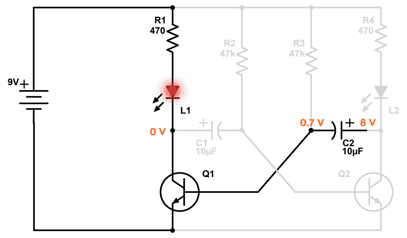
L1 is only lit when transistor Q1 is ON.
We know from how transistors work that Q1 is only turned ON if it has 0.7V on its base. Since the left side of C2 connects to the base of Q1, that means it’s at 0.7V.
The right side of the capacitor C2 connects to 9V through R4 and L2, so it is charging and the voltage is rising. This can sound strange, but at the moment in time when the transistor Q2 turns off, L2 is still on. And current is flowing through L2, charging C2 from the right side. But, the voltage on the right side of C2 reaches around 8V very quickly, turning the L2 off.
A capacitor charges exponentially, which means the voltage rises quickly in the beginning, then slows down more and more. The voltage reaches 7-8V quickly, but from there the voltage rises slowly.
The voltages around transistor Q2
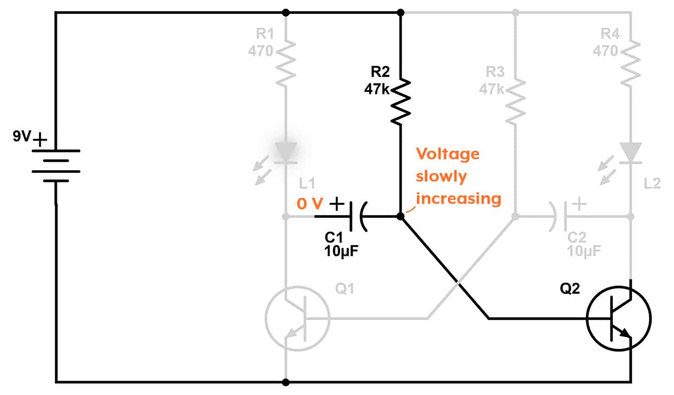
Since the transistor Q2 is off, its base must be lower than 0.7V.
The right side of C1 connects to the base of Q2, so that means this is also lower than 0.7V.
But the right side of C1 is also connected to 9V through the resistor R2, which means it is being charged.
That means the voltage is below 0.7V but rising.
The Turning Point
So, the voltage on the right side of C1 is rising.
And when it reaches 0.7V, the action starts!
When the right side of C1 reaches 0.7V, that means the base of transistor Q2 gets 0.7V on its base and turns on.
…which means the LED on the right also turns on.
But when Q2 turns on, something interesting happens with the voltages we had over the capacitor C2…
Getting a negative voltage
We had that C2 had 0.7V on its left side and 8V on its right side.
Or to say it in another way, the left side was 7.3V lower than the right side.
But now that Q2 turns on, the voltage on the right side of C2 is suddenly pulled down to 0V through the transistor.
The internal charge of the capacitor does not change though, so the left side keeps being 7.3V lower than the right side.
But now that the right side is 0V, that means the left side becomes 7.3V below 0!
Yes, that’s -7.3V.
Transistor Q1 gets minus on its base
With -7.3V on the left side of C2, the base of transistor Q1 also gets -7.3V on its base, which turns it off.
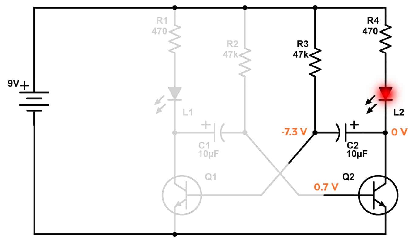
So now, the left LED and transistor have turned off. And the right LED and transistor have turned on.
The left side of C2 starts at -7.3V and is charged through resistor R3 and therefore rising. Since it connects to the base of transistor Q1, when it reaches 0.7V, Q1 turns on again.
And so it continues.
The two transistors keep alternating between on and off, which makes the two LEDs alternate between on and off.
Questions?
I had so much trouble understanding the astable multivibrator circuit when starting out. And it frustrated me because I was thinking it was a simple and easy-to-understand circuit.
But the truth is that you need to have a good understanding of the basics of electronics before you will be able to understand it.
And you should have looked at several much simpler circuits first. Something I take all my Ohmify students through. Curious? Click to learn more about Ohmify.
Did this explanation help you understand the circuit? Or are you just more confused than when starting out? Let me know your comments and questions in the comment field below!
More Transistors Tutorials

Get Our Basic Electronic Components Guide
Learn how the basic electronic components work so that circuit diagrams will start making sense to you.
